


Sparrow WebGL Devlog 4: The Ultimate Wide Line Challenge
WebGL does not support wide lines natively, so I created my own
21.05.2023 - 16:50A few weeks ago, I discovered during Ludum Dare that, unlike OpenGL, WebGL does not support drawing lines wider than 1 pixel, which meant I wasn't able to create the effect that I wanted during the event. To not repeat this scenario, I worked on a custom solution for drawing wide lines this week. It was much more difficult than I expected.
Oh, and I also added a 2D camera.
Wide Lines
In OpenGL, you can use the glLineWidth function to draw wide lines natively, which is very convenient. I always considered this a fundamental feature, so I never even questioned whether it would be available in WebGL too. It was a big shock when I discovered that it isn't (the gl.lineWidth function exists, but it only supports a value of 1 in most implementations). To have access to it anyway, I added custom Line and LineStrip classes to my Sparrow WebGL engine this week. There are a few ways to implement wide line rendering, but I went with expanding the line strip into a triangle strip.
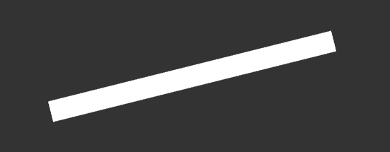
In the simplest case of a single line segment, this is quite easy. You take the line vector and calculate its orthogonal vector, which is then scaled to half the line width and added and subtracted to the start and end points of the line to get the four vertices of the quad.
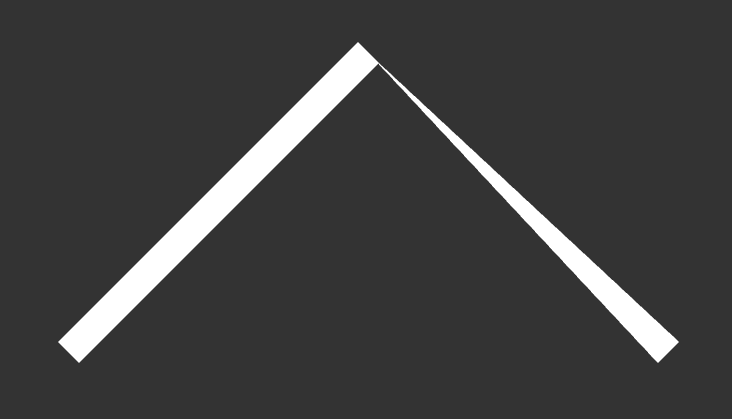
However, as soon as you add a second line segment, this doesn't work anymore (unless they both point in the same direction) because the orthogonal vector for the middle point is influenced by the two line segments. We could just draw two lines, but this creates an ugly artifact in the middle:

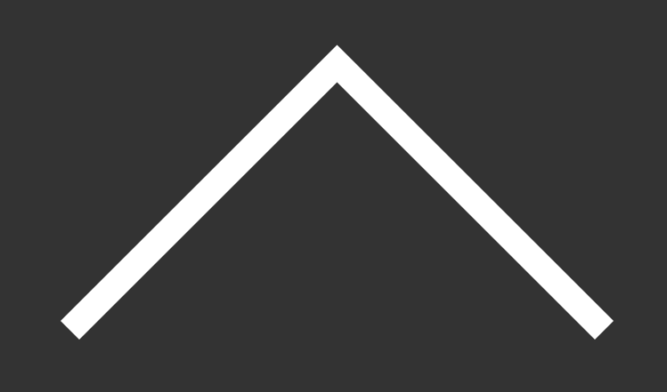
We also cannot take the orthogonal vector of the first line and just continue, because this looks even worse:
Instead, we need to do a little bit of math. As we remember from math class, the dot product of two normalized vectors is the cosine of the angle between them. This means we can take the vectors of both line segments and calculate their angle. Half of that angle will be the angle of the orthogonal vector at the intersection. Additionally, we need to scale the orthogonal vector differently because a rotated vector has to be longer to maintain the original line width. This again, can be done with the angle, the line width, and some basic trigonometry. Now, we can use this information to rotate one of the orthogonal vectors by the angle and scale it to find the positions of the vertices at the intersection and add them to the triangle strip.
Left or Right Turns?
When I had thought about the implementation beforehand, I had only thought up to this point and believed this was the most difficult part and the rest would only be some small implementation details. But boy, was I wrong, because this is when my issues started. First of all, the dot product cosine trick always returns an angle between 0 and 180 degrees, which means a 90-degree turn to the right and a 90-degree turn to the left both return 90 degrees, which is technically correct, but when rotating the vector left and right are either 90 or -90 degrees. Because of this my line class could handle right turns correctly, but left turns were completely messed up. At first, I couldn't come up with a way to detect whether the turn is left or right, but then I found that the determinant of the two line vectors can be used to do this. With it, I could rotate the orthogonal vector correctly in both directions.
The Infinity Problem
However, there was another problem. The smaller the angle between the two line segments gets, the more pointier the intersection becomes.
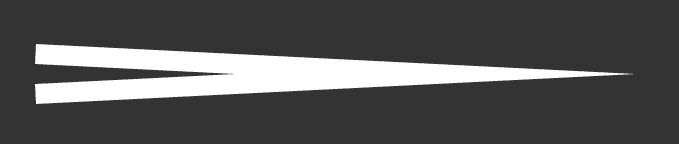
For one, this doesn't look the best for very small angles, but a much bigger problem is the extreme case when the line does a complete 180-degree turn and goes back over itself. In this case, the angle between the two line vectors is 0 and the pointy intersection would go to infinity (this is basically the same problem as the intersection between two parallel lines at infinity). Unfortunately, double precision numbers only go to 1.7976931348623157E+308, which is a lot smaller than infinity, and dividing by 0 is NaN anyway, so we clearly cannot use this method for this edge case. Instead, I added an angle threshold and if the angle is smaller, the intersection changes to a flat end cap instead of a point.
The new intersection method required a bit more math to figure out how to rotate and scale the orthogonal vector, but after a few attempts, I got it correct.
The Flipping Problem
The next, and probably the most annoying problem, was the flipping problem. When you create a triangle strip, the order of the vertices matters. Have a look at this beautiful illustration made in Paint:
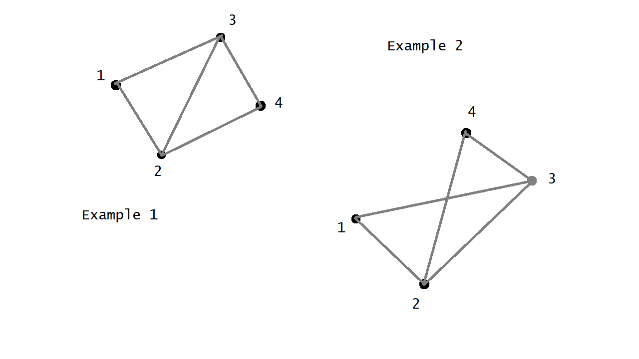
The first triangle is always 1-2-3, and the second one is always 2-3-4, which is how triangle strips work. As you can see, if vertex 2 and 3 are on the same side of the center line, the resulting triangles overlap and there is a very obvious notch in our line, which is a big problem. By chance, this problem didn't occur in my first tests with only two line segments, but once I added the second intersection method for small angles, it popped up.
The two intersection methods worked on their own, but once they were combined in a single line, everything got messed up. I tried for a very long time to find a mathematical solution for this that works in all situations, but I wasn't able to do it. Then I tried to find a workaround by flipping the vertices depending on the previous flip state and angle type and after many attempts, I found a solution that seems to work consistently. To be honest, I do not understand why and how it works, but it will have to do for now. There may or may not be a better solution, but I wasn't able to find it so far.
The Short Line Segments Issue
The next issue was very short line segments. Imagine a line that's 5 pixels long and goes from left to right. It's a line that goes from left to right, obviously. Now, imagine that same line but it's 50 pixels wide. Because our line is very short but extremely wide, it looks like it goes from top to bottom even though it's still the same left-to-right line.

For straight, single-segment lines this isn't even the biggest problem, but for multi-segment lines with bends, it looks very bad. However, I don't think this problem can be fixed in code, because it always depends on the scenario the line is used in and picking an appropriate width for that use case.
Zero Length
As mentioned, short line segments cause some problems. The extreme case for this is a line length of 0, i.e. the start and end point of the segment are identical. At this point, most of the calculations break down because of division by zero and other issues. It's not possible to calculate the correct vertices any more.
The obvious, and easiest, solution for this is to remove all duplicate points from the input, which is what I did at first. However, because of pass-by-reference, this altered the original data outside of the line class, which is bad. This meant I either had to create a deep copy of the data or find a different solution that doesn't change the points. After some consideration, I found a different solution. If a line segment is zero, we need to find the next or previous line segment with a non-zero length and use that as the basis for the calculations instead. With some special cases for the start and end segments of the line, this solution seems to work.
It probably was a waste of time
Implementing wide lines was a lot more difficult than I expected. I knew it would be challenging to get some of the math right, but I couldn't imagine how many edge cases and other issues there were. Realistically, wide lines aren't even that important. I don't know that many use cases for them in game development, but once I got started on this side quest, I had to see it through.
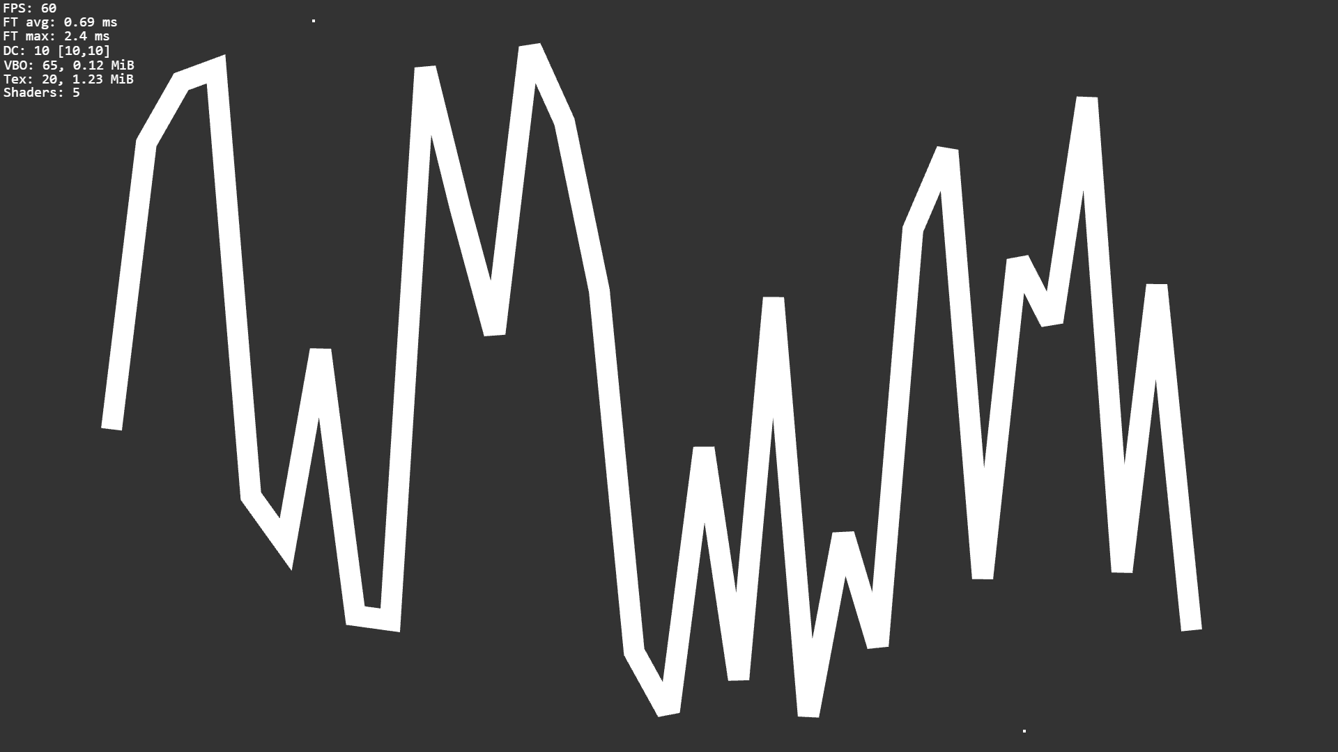
The code seems to work in most situations. I randomly created a bunch of lines to see if there are any problems and it seemed okay, but I don't fully trust it yet. I'm sure there are still some edge cases I haven't considered and I'll stumble upon them in the most inopportune moments in the future.
2D Camera
I also implemented a 2D camera this week, which was a breeze compared to the wide lines. I took the 2D camera of my OpenGL/C++ engine as a starting point and continued from there. Unlike the original version, which only supports camera movement, I wanted to add zoom to the WebGL implementation. Zooming in 2D is just scaling, so it was easy to add, but what took a bit of time to get working was zooming in at the position of the mouse, which also requires a translation depending on the position of the mouse pointer. As for movement, the camera supports dragging and scrolling at the edges. Most camera behaviors and values can be controlled with an options parameter, which hopefully makes it very versatile.
Misc
- added a new Mesh2D super class for all 2D shapes
- fixed a bug that caused blurry lines because UI elements were not pixel aligned on non-even canvas dimensions
by Christian - 21.05.2023 - 16:50